Sunday, October 31, 2010

WS3A


TPS (linear)
This TPS oscilliscope pattern is showing that the engine has started accelerating smoothly from idle. The TPS works by supplying a 5V reference to the potientiometer this read by a 'wiper' which connects with a different part of the potientiometer depending on how far the throttle pedal is depressed.
My theoretical fault is there is resistance in the earth wire.
For example the potientometer is 10k ohms, the resistance in the ground wire is 3k.
The throttle is at halfway.
Calculations.
R1=5000 R2=5000 R3=3000 RT=13k
5V/RT=0.000348 x R1=3.08 5-3.08=1.92
1.92/R2+R3=0.000385 x R2=1.925
1.92+1.92=3.84
5-3.84=1.16(R3)

So the signal sent to the ECU would be 3.84 for half throttle, but really the proper voltage for half throttle would be 2.5V.
As the ECU does not know any better it will adjust the air/fuel mix for a higher,roughly 2/3 throttle instead of half, which will cause the engine to run rich, which will effect performance and fuel efficiency.


IAT
The IAT and ECT work the same way. Both the sensors are NTC thermistors, this means that when the temperature increases they will decrease in resistance. It can range from 24000 ohms to 200ohms, all depending on the temperature.
In this picture the IAT sensor is being warmed up, as this happens it is slowly decreasing in resistance.

The ECT and IAT work by voltage drop. There is a 5Vsupply, followed by set resistor which is in series with the sensor. The ECM is able to calculate the temperature by reading the Vd across the set resistor. The set resistor will change in Vd as the sensor warms up. When the sensor is cold the set resistor will have less resistance, giving it a low Vd. As the sensor warms up and the difference in resistance is reduced the Vd will decrease over the sensor and increase over the set resistor. As this continues the set resistance will become greater that the sensors resistance and will have a large Vd across it. Using this Vd the ECM can tell the temperature.
If there was a resistance in the ground wire this would cause a fault which would mean the Vd over the set resistor would not be accurate as it would b
e Vd across the extra resistance also.

eg.
4500 ohm set resistor, and the temperature is 40C, so around 1100 ohms. VS=5V
4500(R1)+1100(R2)+400(R3)=6000(RT)
Vs/RT=0.000833
R1 x 0.000833=3.74
Vs-3.74=1.26
1.26/R2+R3=0.00084
R2 x 0.00084=0.924
3.74+0.924=0.336
R3 creates a 0.336 Vd.
So the set resistor is Vd 3.74 but it should be 4.014(did the same calculations for a normal reading), this will give the ECM a inaccurate reading.


ECT
The IAT and ECT work the same way. Both the sensors are NTC thermistors, this means that when the temperature increases they will decrease in resistance. It can range from 24000 ohms to 200 ohms, all depending on the temperature.
On this ECT sensor, at 20C it was around 2.7k ohms and as it warmed up the temperature reached 100C at 200 ohms.
If the set resistor (R1) is 20k ohms, the sensor is at 70C which is 400 ohm(R2)
There is a resistance in the ground wire of 8k ohms(R3).
R1+R2+R3=28.4k ohms (RT)
5V/28.4k=0.000176 x R1=3.52Vd
5-3.52=1.48
1.48/R2+R3=0.000176 x R2=0.7+3.52=3.59
5-3.59=1.41R3

As the voltage drop is lower of R1 than it should be, the ECM receives the wrong reading which effects the performance of the engine as they ECM will think its colder than it really is.

MAP
This oscilliscope pattern is showing me that there is little pressure going through the intake manifold. So that means the engine is idling, and at WOT the engine would show 5V as the pressure increases. The way the voltage is increased by pressure is that there is a reference chamber of pressure, a known pressure. This is seperated by a silicon chip, to the air pressure of the intake manifold. When the pressure increases the silicon chip changes its resistance which effects the output voltage.


Calculations
R1=14k ohms
R2=7k ohms
R3=6k ohms
R4=10k ohms
R5=19k ohms
RIN=2k ohms
RF=5k ohms

A= R1+R2+R5=RT1 (40K)
5V/40K=0.000125 x R1=1.75Vd at R1
5V-1.75V=3.25 at point A

B=R3+R4+R5=RT2(35k)
5V/35k=0.000125 x R4=1.428exp-4 x R4=1.428Vd at R4
5V-1.428=3.572V at point B

RIN
B/Rin=0.001786

MAF
The MAF sensor is used to measure the amount of air(mass).
At A the engine is accelerating hard WOT, increasing the mass airflow.
At B the car is decelerating to about half throttle.
At C the car is accelerating smoothly up to WOT.
At D the car is off the throttle, but the engine is still slowing down which is still drawing air in.
At E throttle is blipped increasing the air flow for a split second.

Calculations
Platinum wire=R1=34K Ohms
B-earth=R2=15k Ohms
Bad earth=R3=58K Ohms
RT=107K Ohms
5V/RT=4.672exp-5
R1 x 4.672exp-5=1.588
5-1.588=3.412V output at B

As there is a big resistance in the earth circuit, it draws voltage away from the lessers resistors, R1 and R2 and uses most of the voltage over R3. This effects the voltage at B as there would be less Vd across R1 as the voltage is needed down at R3. So there would be a higher reading at B.

WS3 Oscilloscope patterns


TPS(switch)
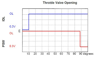
With the engine start the idle circuit is on to keep it running at the optimal air/fuel mix. As this is not a sensor but a switch, the ECU will not change the air/fuel mix until the switch changes to the WOT circuit. This will not happen till the throttle is depressed to 88degrees, at this point the switch activates and the WOT circuit kicks in, while the idle circuit stops. This tells the ECU that the engine is at needing an increased air/fuel mix so it can accelerate faster.

Oxygen Sensor
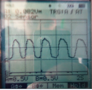
This pattern is showing the O2 sensor in closed loop. Open loop would be when the O2 sensor is not active, everytime you turn your car on the O2 is in open loop until it warms up to operating temperature. Closed loop is when the O2 sensor is cycling the air/fuel mix to evenly burn. It does this by sending its signal to the ECU which adjusts the air/fuel mix accordingly. When the air/fuel mix is lean it shows little voltage around .2V and when running rich its around .9V.


Hall Effect distributor
A=This is the dwell time
B=This is the firing time
C=This the peak voltage
The hall effect distributor works by passing a crystal by a magnet.
This means the electrons in the crystal are moving perpendicular to the magent. That then causes the electrons to get pulled to one side, giving a difference in voltage, which is then amplified by an op amp, which turns on the transistor.


Rpm sensor
This is the Rpm sensor, this is really showing the magent in the distributor at work. As the pole peice approaches the magnet, the voltage starts to increase as the air gap is getting smaller.
When the air gap is at its smallest the magnetic field is at its strongest at has fully saturated the trigger coil. As the pole peice or reluctor wheel moves away from the magnet, the magnetic field induced in the coil collapses and sends a negative voltage( a voltage in the opposite direction).
Then the next pole peice starts to come round and the cycle continues...

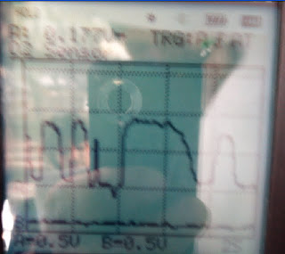
Injector pulse
The pattern us showing the injector being opened and closed. In the first square, this is showing the 12V supply. In the second square you can see the voltage drop to almost 0 as it is earthed, this is when the injector is open. In the fourth square the injector is turned off, this creates a back emf, in some cars this is used to charge the capacitors. In the 5th square, this shows the back emf fading as the injector returns to its normal 12VS.
If this injector pulse was faulty, this could effect the fuel/air mixture. If the injector stayed open to long it would let to much fuel though. This would flood the cylinder and cause the engine to run rich. This would then produce bad emissions and also reduce the power of the engine.

MAP(Manifold absolute pressure sensor)
This is a picture of a map sensor, while it was at idle. If the diaphragm had been damaged, it may not reach its max or min voltage. This could effect the output voltage to the ECU, which then is using the wrong information to run the car, which would obviously cause the car to become rich or lean. The higher the voltage the higher the pressure. So if the car was at idle like shown, it would raed around .8V-1V. At WOT the voltage would read at 5V.

Alternator Output
This pattern is showing that the AO is working correctly, as it is putting out 14.6V. If this was a faulty alternator, we would be able to see a lower voltage. Also if faulty the alternator would put out voltage spikes which you would be able to see with the oscilliscope. This is the alternator output, this shows that the alternator in my car is putting out 14.5V while it is running. If the alternator belt was slipping, it would not produce the voltage needed to charge the battery and run the some systems on the car.

Thursday, September 30, 2010

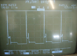
WS8 Primary and Secondary Igniton Patterns

Firing Voltage 45V
Burn Voltage 12V
Burn Time 1.4ms
Dwell time 4ms

This picture of the primary waveform is very important. It tells you many things. For example it can show you that one cylinder has a high resistance, by having a very high firing voltage. It can tell you other information such as the burn time. This will show you how long it takes to burn the fuel while its in the cylinder.


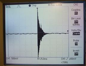
This video shows the engine doing a snap acceleration. The oscilliscope is measuring the secondary pattern.
Using a spark tester on the 1st cylinder I increased the gap so that it would require more voltage to jump the gap. As you can see in the picture, the voltage went off the chart. This shows you that the slightest resistance in any wire will ultimately effect your ignition in the cylinder.

WS7 Exhaust Gas Analysis

With the gas analyser sensing normal air, the gas readings are
C0 0.001%
HC 15
Co2 0.01%
02 21.23%
These readings show the air around us, without much contamination.

With the engine idling while cold you get these readings:
CO 1.038
HC 156
Co2 14.42
O2 0.82%
As the catalytic converter has not warmed up yet, the car is emitting a lot of CO.


3.The engine has warmed up now and the readings are:

CO .727

HC 181

CO2 13.49

O2 1.9

This shows that the catalytic converter has started to work to reduce emissions.

4. The engine is warmed up and running at 2500 RPM the readings are:

CO 5.5

HC 419

CO2 11.14

O2 0.29

As the engine is at a faster speed, it obviously must produce more emissions.

5. At idle with a richened fuel/air mix the readings are:

CO .707

HC 100

CO2 14.08

O2 0.45

I don’t think I made the mixture rich enough as the readings were the same as the engine warmed up.

6. At idle with a lean mixture the readings are:

CO 0.129

HC 66

CO2 13.92

O2 2.54

As there is an air leak, the O2 reading is high.

7. Under acceleration the readings are:

CO .676

HC 198

CO2 8.03

O2 .192

As the mixture gets richer with acceleration, the CO reading will get higher.

8. Disconnected spark plug wire grounded by a jumper wire, and the readings are:

CO 2.3

HC 3978

CO2 9.06

O2 8.27

As one cylinder is not having its fuel/air mix burnt all the readings will skyrocket.


Disconnected one injector, the readings are:

CO 737

HC 270

CO2 8.82

O2 8.6

Showing that the injector is open, as there is more fuel being unburnt.


The readings on a car without a catalytic converter would show that there is an excessive amount of CO,HC and CO2 that is being put into the atmosphere. As the ‘cc’s job is to reduce these emissions.

A car with a cc would have far less emissions once the cc has warmed up to operating temperature. The cc then converts CO and HC into CO2 and H2o.


O2 sensors can have many wires.

  • One is for the positive heater.
  • One is for the negative heater
  • One is the output to the ECU
  • One is for the temperature

Ws5 Scan tool diagnostics

I put this scan tool onto my Mzada capella 98. I used the correct plug and put it into the diagnosis plug on the car.


I got these readings off the cars live data.
There were no fault codes.
I unplugged some sensors and rediagnosed the car.
There was three fault codes now.
p0100 MAF sensor malfunction
P0100 IAT Circuit malfunction
P0505 Idle control system Malfunction

The IAT was the one we noticed still gave us a reading, even though it was unplugged. The ECU obviously has a preset IAT reading if the IAT is not working, in this case it was at 19*C.
The MAF gave me no reading at all, and the Idle control circuit just stayed off.

I repaired the faults and all the fault codes were cleared via the scan tool. I then rediagnosed the car and no fault codes came up.

Live data is a great way of fault finding, as it is 'live'. So you can see the problem first hand. This can save a lot of time when working in a workshop.

WS4 Fuel Pressure and Flow

The fire extinguishers can be found in the corner of the class.
The fuel pressure spec on the toyota A4-fe is 265-304KPa.

To install the pressure gauge, you must relieve the pressure in the system first. You can do this by removing the fuel pump fuse and then cranking the engine. The gauge was properly installed and there was no fuel leaks.
The gauge read 200 KPa.
At idle the gauge read 25o KPa.
Maximum pressure of 400 KPa.
WOT of 300KPa.
The Residual pressure was 250KPa.
The flow is 2.2L per min.

I then uninstalled the gauge. I refitted the hoses, double checked them.
I cranked the engine to check for leaks before starting it. It ran fine.
It is important to know how the fuel system works, as it can help to find leakages and/or blockages.

Symptoms of a vehicle with these problems:
Low fuel pressure:
It would be unable to idle.

Low fuel flow:
The car would run lean as there is not enough fuel being injected.

High fuel pressure:
The car would run rich as the injectors would be forced to stay open longer than necesscary.

Faulty fuel regulator:
Car would be jerking, or just not run at all as it starves for fuel.

WS2- Flash codes

We created 3 fault codes on the toyota 4a-fe engine. To make the flash codes come up on the dash, you must use a jumper wire across terminals TE1 and E1 in the diagnosis plug. The flash codes came up as 12, 22, 31 and 41.

12 was G-NE signal circuit which we found to be the distributor clearance was to big. This was a real fault on the engine.
22 was the ECT unplugged.
31 was the MAP unplugged.
41 was the TPS unplugged.

To clear these codes, we disconnected the negative terminal on the battery. On a new car this would not be acceptable, you would have to remove the appropriate fuse.

We rechecked the codes, and got a constant flashing light. This means everything is ok.

As we unplugged some critical sensors, the ECU would've have insufficient information to run the car at its optimum.

When everything is returned to its original place, turn the engine on and rev it to double check all is ok.

Wednesday, September 29, 2010

Back Probing

Back probing is used to test electrical circuits without disconnecting or damaging terminals.
You can do this by inserting a pin down the wire at the terminal to get a reading.
Using a multimeter set to ohms you must touch the ohm meter together to get the ohmmeter resistance, which was 2 ohms. I measured a wire by back-probing at each terminal. I got a reading of 2.5 ohms. I then minus the 2 ohms, to get the wires resistance of 0.5 ohms.

This shows that I had connectivity by back-probing as I didn't get an infinite reading.

Tuesday, September 28, 2010

Vane Air Flow Sensor


The air flap is connected to a potentiometre which then effects the output volatage as the air flow changes. This Vane Flow Sensor does not meet specifications. I think there is extra resistance in the potentiometer as at idle the voltage does not even reach 4V.

Monday, August 30, 2010

Oxygen Sensor and WS6

The oxygen sensor is found on the exhaust manifold.
My oxygen sensor has 4 wires, and is a zirconia type switching sensor.
The max voltage is around 0.9V and the min is about 0.1V.
At idle this sensor read 10 cross counts in 10 seconds.
This picture is from 1997 Encyclopedia Britannia, Inc


This shows sudden deceleration this shows the mixture going lean, and giving a low voltage of 0.15V


This shows sudden acceleration as the mixture turns rich, and gives a high voltage. Reaches 0.9V at max.

This shows the response time of the O2 sensor. It takes roughly 100ms to fully change the fuel/air mix via the O2 sensor to ECU.

This is at 2500RPM, as it is cruising the ECU is oscillating the fuel/air ratio to keep emissions down. As its at 2500 it oscillates quicker than at idle.

At idle this shows us that the air/fuel mix is changing to try and burn rich and lean, so that it produces the least amount of emssions.

I've found that my O2 sensor is a critcal part of the car, and thankfully it is working properly. Without this sensor, the car would fail emission tests and fuel economy tests.

Knock Sensor


Knocking happens when the advance timing in the enigine, is too advanced. This causes vibrations and movement of the cylinders from side to side. This leads to loss of power and increased engine wear.

The Knock sensors works by sending a voltage to the ECU. The voltage is created by the friction of the peizo crystals inside the knock sensor. When the knocking increases a higher voltage is sent to the ECU which then retards the timing.

Intake Air Temperature

The IAT sensor does not meet the manufactures specifications. At 20*C its resistance is 2.1K ohms, when it should be 2k. At 80*C its resistance is 300 ohms, when it should be 20 ohms.

This type of thermistor is an NTC.

As I've observed the air and coolant sensors, I've noticed that as the sensors get hotter the resistance drops.

Thermo Fan Switch


The Fan switch does meet the specifications as it switches at the correct temperature, of around 90*C. This activates the fan to help cool the coolant.

This is not a thermister as a thermister changes its resistance according to its temperature. The thermo fan switch is obviously a switch and does not vary its resistance until it reaches the point of switching.

The internal operation of this sensor is an NTC resistor, and this changes resistance as the temperature changes.

Engine Coolant Temperature

The sensor works using a 5V reference which is effected by the resistance. When cold the resistance is high, there it will send a reading of around 0.5v to the ECU. As the coolant warms up the resistance drops. So you'll get a reading of around 4.5 to 5V when at operating temperature. This graph shows that the ECT sensor drops in resistance as it warms up, this will affect the output signal.

Mass Air Flow Sensor


When the MAF was turned on it gave us a voltage of 1.06V, without passing air over the sensor.
I then increased the air flow, as I did this the voltage increased to 2.55V.
The specifications of a MAF are at 1V-4.5V.

Testing Ignition Coils

Testing ignition coils.
Coil No.1 3IC2R Coil No.2 3IC2R
Coil Voltage 12 12
Coil Primary 11.2/8.2 11.2/8.2
Coil Secondary 9k 1.

The difference in these two coils, although exactly the same modle

Wasted Spark Coil Pack
No.1 No.2
Coil Primary N/A N/A
Coil Seconday 5.65K 5.81K

Wasted spark ignition works by firing two cylinders with one coil . Everytime a spark is fired two cylinders are fired but as only one cylinder needs the spark, the other cylinder is 'wasted'.


Ballast Resistor specs
BR3 BR2
1.5-1.7 ohms 0.5-0.7 ohms
Measured resistance
1.7 ohms 0.6 ohms

The ballasts resistors purpose is to limit current from the battery to the coil. This will prevent heat building up inside the windings and buring them out causing a short.

Injector testing and WS1


Another engine problem that could give the same result as an injector not firing could be a bad earth circuit. This could be something as simple as the battery negative being corroded.
When removing fuel injectors from the engine you must depressurize the system beforehand. The manufactures specs for injector leakage is 2 drips per min.
And for flow rate 5% cc. per minute max to min.

Three injectors require attention.
No.1 injector had an offset spray pattern.
No.2 injector had a leakage problem.
No.4 injector spray pattern was a combination of offset and poor atomisation.
No.3 injector was the only injector in good condition.

Petrol fuel injector testing.
Battery V inj1 inj2 inj3 inj4
13.5V 13.12 13.42 13.23 13.33
Injector is firing yes yes yes yes
Duty cycle at idle(%) 50.6 50.7 50.8 50.2
Duty cycle at 2500RPM(%) 42 46.7 42.8 45.3
Hz at idle .564 .586 .587 .584
Hz at 2500RPM 14.8 9.4 10 9.07

I found that duty cycle was a better way of measuring, as the hertz reading on the screen get flickering and I couldnt get a decent reading.

Manifold Absolute Pressure

The MAP sensor doesn't quite match the specifications. It follows the same constant pattern of the more vacuum the less voltage but the idle voltage starts higher at around 4.8V before dropping down to almost zero.

The MAP sensor reads the vacuum or negative pressure.

The MAP sensor works measuring the pressure in the intake manifold it does using a membrane to seal the reference chamber, as the pressure increases the membrane deforms and produces a voltage. The higher the pressure in the manifold the more the membrane will deform more and therefore the higher the output voltage.

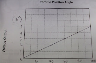
Throttle Position Sensor

This is TPS is a variable type resistor.
This type of TPS works by varying a set voltage being *read* by the ECU at different points on the resistor. At WOT there is less resistance and so there is more voltage. At idle there is the most resistance, and so the least voltage.


As this TPS is a switch, at the set resistance the circuit will change to the circuit specified to that resistance.

Sunday, August 1, 2010

Speed Sensors

Optical distributor, this shows the rotor blade switching the light on and off within the distributor. This sends a voltage through to the spark plugs when its turned on.

Hall effect distributor, this switiches the voltage on and off using teeth. As the rotor teeth pass by the stator teeth, this creates a magnetic field which then collapses. Giving the pattern above.

This is the waveform of the Rpm sensor. This shows that the back emf by breaking the magnetic field created by passing the magnets passed each other, creates a negative voltage. The more cylinders the more sections on the pattern.