Monday, August 30, 2010

Oxygen Sensor and WS6

The oxygen sensor is found on the exhaust manifold.
My oxygen sensor has 4 wires, and is a zirconia type switching sensor.
The max voltage is around 0.9V and the min is about 0.1V.
At idle this sensor read 10 cross counts in 10 seconds.
This picture is from 1997 Encyclopedia Britannia, Inc
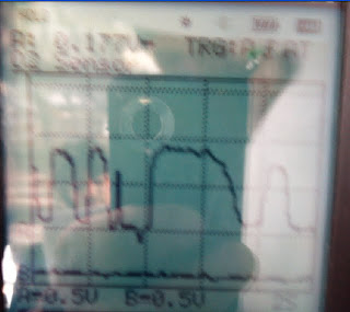


This shows sudden deceleration this shows the mixture going lean, and giving a low voltage of 0.15V


This shows sudden acceleration as the mixture turns rich, and gives a high voltage. Reaches 0.9V at max.

This shows the response time of the O2 sensor. It takes roughly 100ms to fully change the fuel/air mix via the O2 sensor to ECU.

This is at 2500RPM, as it is cruising the ECU is oscillating the fuel/air ratio to keep emissions down. As its at 2500 it oscillates quicker than at idle.
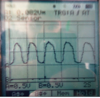
At idle this shows us that the air/fuel mix is changing to try and burn rich and lean, so that it produces the least amount of emssions.

I've found that my O2 sensor is a critcal part of the car, and thankfully it is working properly. Without this sensor, the car would fail emission tests and fuel economy tests.
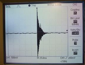
Knock Sensor


Knocking happens when the advance timing in the enigine, is too advanced. This causes vibrations and movement of the cylinders from side to side. This leads to loss of power and increased engine wear.

The Knock sensors works by sending a voltage to the ECU. The voltage is created by the friction of the peizo crystals inside the knock sensor. When the knocking increases a higher voltage is sent to the ECU which then retards the timing.

Intake Air Temperature

The IAT sensor does not meet the manufactures specifications. At 20*C its resistance is 2.1K ohms, when it should be 2k. At 80*C its resistance is 300 ohms, when it should be 20 ohms.

This type of thermistor is an NTC.

As I've observed the air and coolant sensors, I've noticed that as the sensors get hotter the resistance drops.

Thermo Fan Switch


The Fan switch does meet the specifications as it switches at the correct temperature, of around 90*C. This activates the fan to help cool the coolant.

This is not a thermister as a thermister changes its resistance according to its temperature. The thermo fan switch is obviously a switch and does not vary its resistance until it reaches the point of switching.

The internal operation of this sensor is an NTC resistor, and this changes resistance as the temperature changes.

Engine Coolant Temperature

The sensor works using a 5V reference which is effected by the resistance. When cold the resistance is high, there it will send a reading of around 0.5v to the ECU. As the coolant warms up the resistance drops. So you'll get a reading of around 4.5 to 5V when at operating temperature. This graph shows that the ECT sensor drops in resistance as it warms up, this will affect the output signal.

Mass Air Flow Sensor


When the MAF was turned on it gave us a voltage of 1.06V, without passing air over the sensor.
I then increased the air flow, as I did this the voltage increased to 2.55V.
The specifications of a MAF are at 1V-4.5V.

Testing Ignition Coils

Testing ignition coils.
Coil No.1 3IC2R Coil No.2 3IC2R
Coil Voltage 12 12
Coil Primary 11.2/8.2 11.2/8.2
Coil Secondary 9k 1.

The difference in these two coils, although exactly the same modle

Wasted Spark Coil Pack
No.1 No.2
Coil Primary N/A N/A
Coil Seconday 5.65K 5.81K

Wasted spark ignition works by firing two cylinders with one coil . Everytime a spark is fired two cylinders are fired but as only one cylinder needs the spark, the other cylinder is 'wasted'.


Ballast Resistor specs
BR3 BR2
1.5-1.7 ohms 0.5-0.7 ohms
Measured resistance
1.7 ohms 0.6 ohms

The ballasts resistors purpose is to limit current from the battery to the coil. This will prevent heat building up inside the windings and buring them out causing a short.

Injector testing and WS1


Another engine problem that could give the same result as an injector not firing could be a bad earth circuit. This could be something as simple as the battery negative being corroded.
When removing fuel injectors from the engine you must depressurize the system beforehand. The manufactures specs for injector leakage is 2 drips per min.
And for flow rate 5% cc. per minute max to min.

Three injectors require attention.
No.1 injector had an offset spray pattern.
No.2 injector had a leakage problem.
No.4 injector spray pattern was a combination of offset and poor atomisation.
No.3 injector was the only injector in good condition.

Petrol fuel injector testing.
Battery V inj1 inj2 inj3 inj4
13.5V 13.12 13.42 13.23 13.33
Injector is firing yes yes yes yes
Duty cycle at idle(%) 50.6 50.7 50.8 50.2
Duty cycle at 2500RPM(%) 42 46.7 42.8 45.3
Hz at idle .564 .586 .587 .584
Hz at 2500RPM 14.8 9.4 10 9.07

I found that duty cycle was a better way of measuring, as the hertz reading on the screen get flickering and I couldnt get a decent reading.

Manifold Absolute Pressure

The MAP sensor doesn't quite match the specifications. It follows the same constant pattern of the more vacuum the less voltage but the idle voltage starts higher at around 4.8V before dropping down to almost zero.

The MAP sensor reads the vacuum or negative pressure.

The MAP sensor works measuring the pressure in the intake manifold it does using a membrane to seal the reference chamber, as the pressure increases the membrane deforms and produces a voltage. The higher the pressure in the manifold the more the membrane will deform more and therefore the higher the output voltage.

Throttle Position Sensor

This is TPS is a variable type resistor.
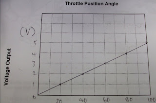
This type of TPS works by varying a set voltage being *read* by the ECU at different points on the resistor. At WOT there is less resistance and so there is more voltage. At idle there is the most resistance, and so the least voltage.


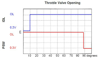
As this TPS is a switch, at the set resistance the circuit will change to the circuit specified to that resistance.

Sunday, August 1, 2010

Speed Sensors

Optical distributor, this shows the rotor blade switching the light on and off within the distributor. This sends a voltage through to the spark plugs when its turned on.

Hall effect distributor, this switiches the voltage on and off using teeth. As the rotor teeth pass by the stator teeth, this creates a magnetic field which then collapses. Giving the pattern above.

This is the waveform of the Rpm sensor. This shows that the back emf by breaking the magnetic field created by passing the magnets passed each other, creates a negative voltage. The more cylinders the more sections on the pattern.